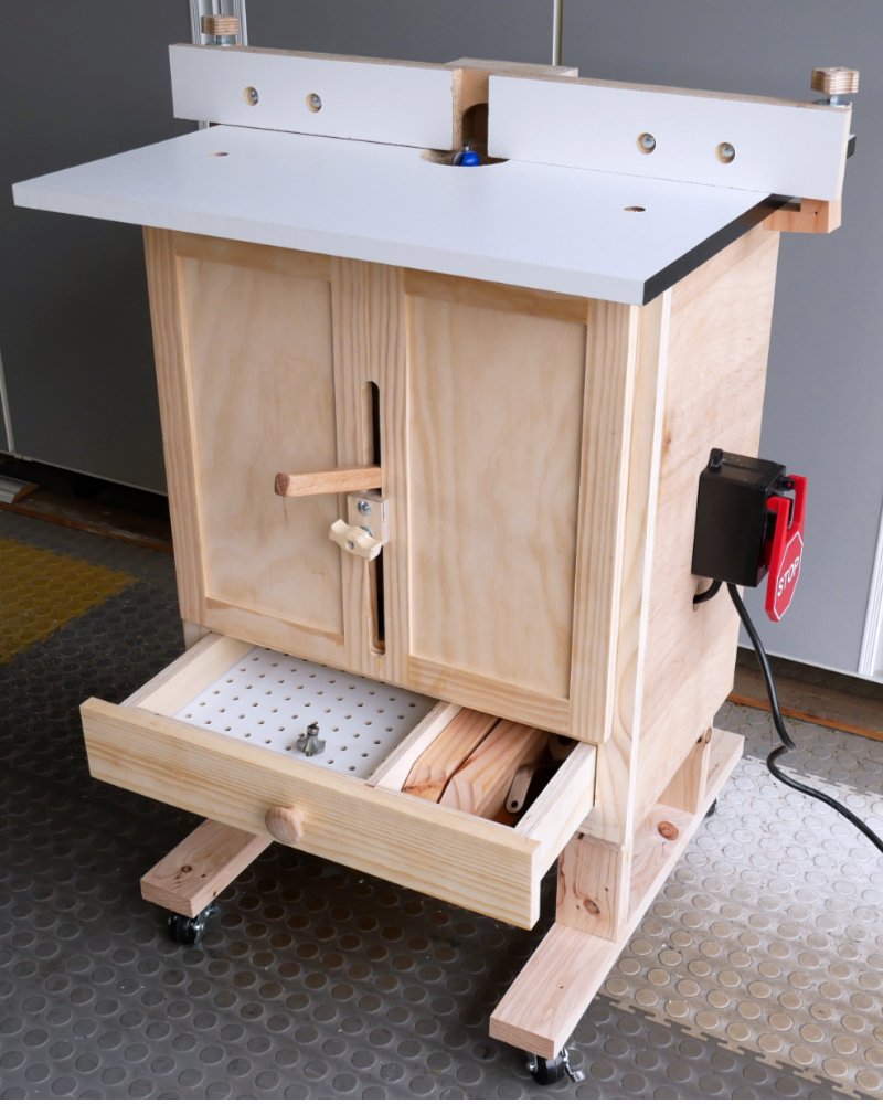
 I just finished a highly customized version of the “Benchtop” Router Table from Steve Ramsey’s “Powered Up” online course. I put “benchtop” in quotes, because it ended up being a floor-standing router table.
User’s Guide
This article serves as documentation for the build, but also as a sort-of user’s guide for whoever ends up owning this table.
The table comes fully assembled, but in order to familiarize you with the various components, let’s walk through the assembly steps.
The Stand
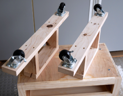 I’m starting with the router table upside down, to show you the custom stand.
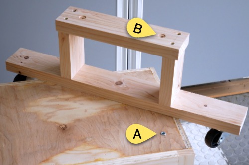 The bottom of the router table has four threaded inserts (“A”). Since they stick out from the bottom a little, I put matching counterbores in the legs (“B”).
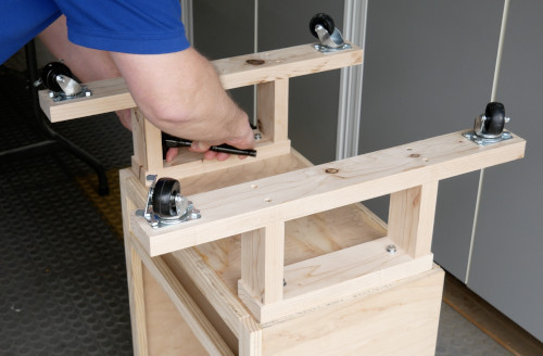 The legs are attached with bolts, washers, and lock washers.
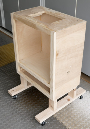 And here it is, right-side up.
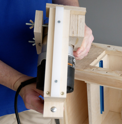
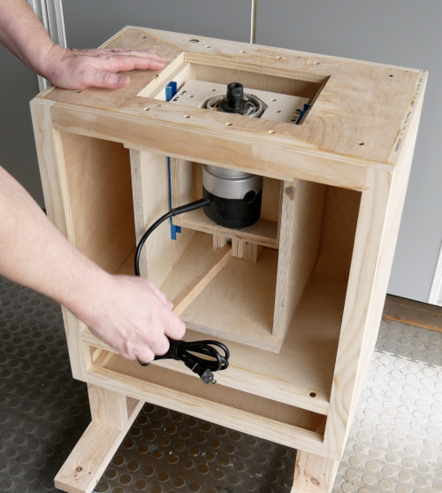
The Lift
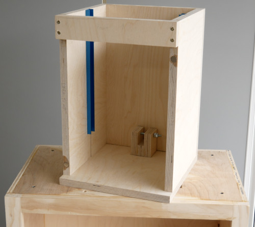 Here’s the housing for my DIY Lever Operated Router Lift, which is included with the router table.
Watch the build video for more information.
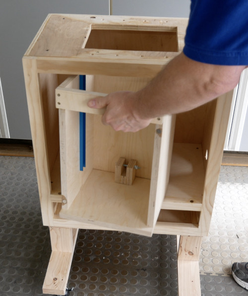 The housing goes in the body of the cabinet, and will get screwed into the top through the pre-drilled holes.
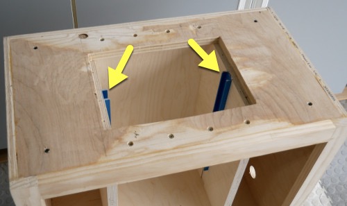
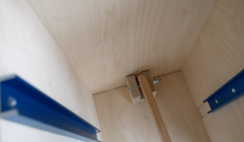
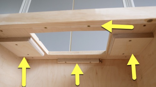 This is looking up into the inside of the table. There’s four wooden guides…
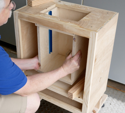 …that align the lift perfectly with the pre-drilled holes in the top.
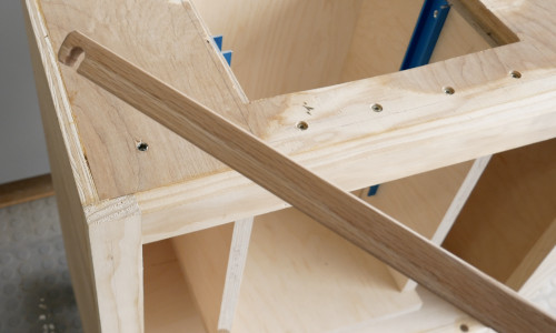
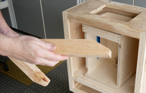 The supplied blocks…
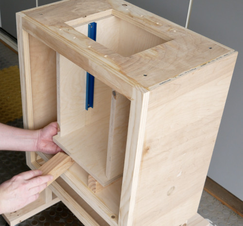 …are used to keep it in place…
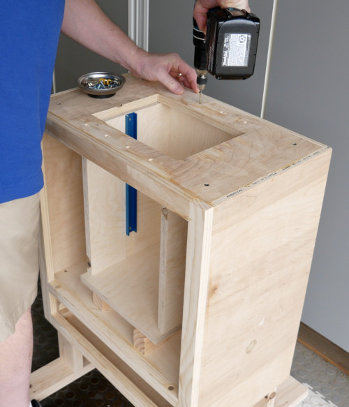 …while you drive the screws.
The lift is made out of Baltic Birch plywood, and the screws are Spax screws, so the lift can be installed and removed many, many times without fear of it becoming unstable.
Not that there’s really any reason to remove it.
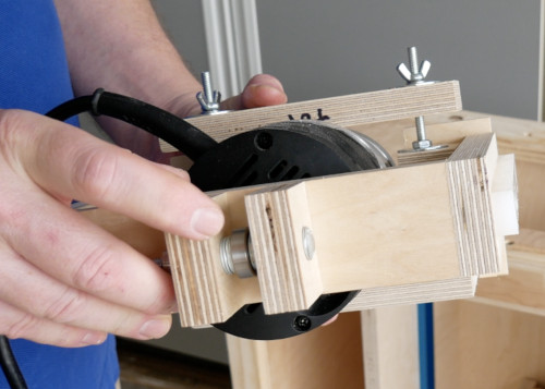
The Carriage
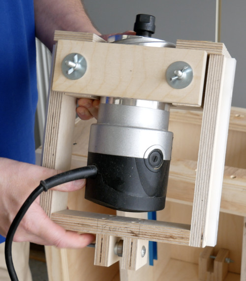 Here’s the carriage, which holds the router.
You can either supply your own router, or buy this one from me.
 The carriage has runners on the side…
 …which go into the miter tracks in the lift housing.
 You raise and lower the carriage using this lever…
 …which goes over the bolt that acts like a fulcrum.
 There’s a bearing on the bottom of the carriage…
 …that rides on the lever, when you raise and lower the carriage.
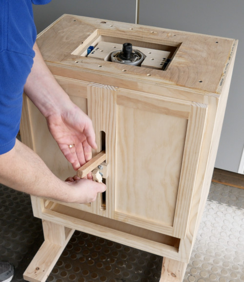
The Router Lift Door
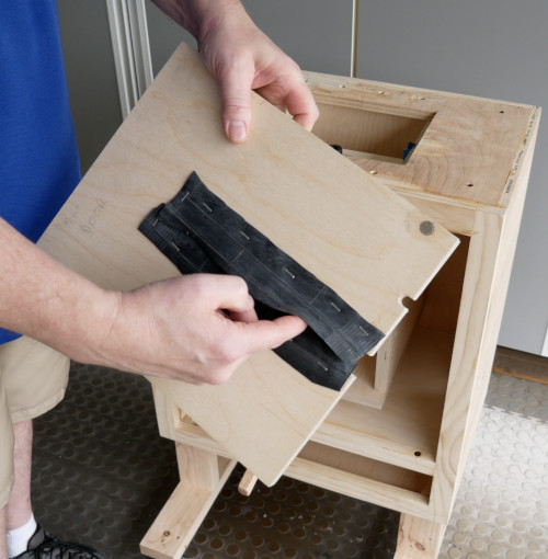 The door to the router lift has a slot for the lever, and some pieces of bicycle tubing to help keep the dust inside the lift housing.
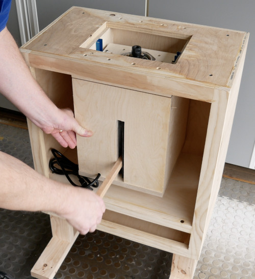 The door is held on by magnets, and you can also see the hole for the power cable.
The Router Cabinet Door
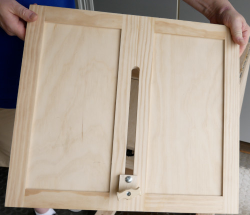 Here’s the cabinet door.
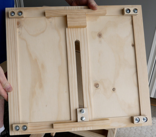 It has four adjustable magnetic blocks…
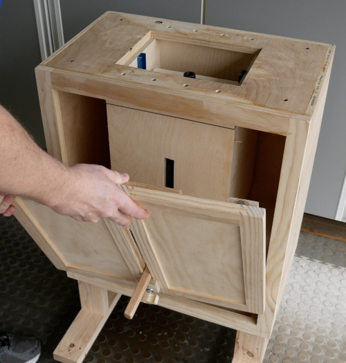 …which fit snugly into the four corners of the cabinet…
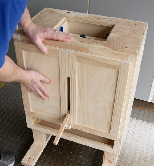 …so the door stays put…
 …when you use the lever clamp.
The Drawer
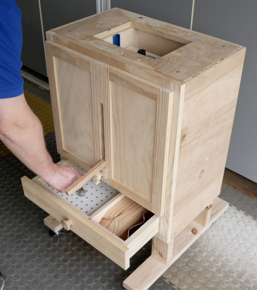 The drawer has a place to store the blocks and the wrenches (or whatever else you want to put there), as well as a place to store bits.
The Top
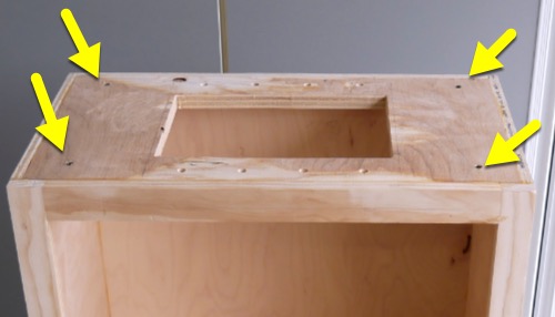 The top of the router cabinet has four threaded inserts…
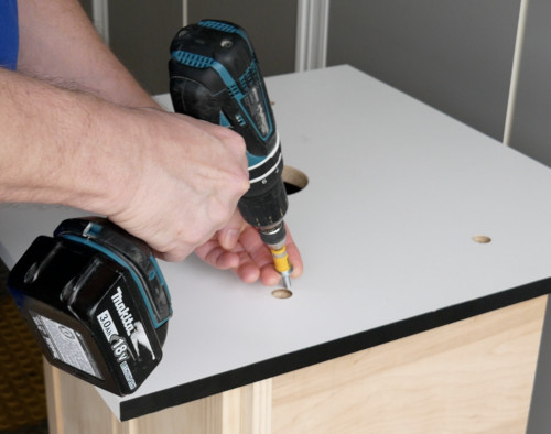 …so the melamine top can be attached and removed easily, if needed.
The Fence
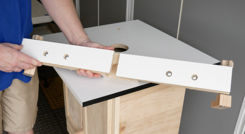 The fence is your basic split-front router fence.
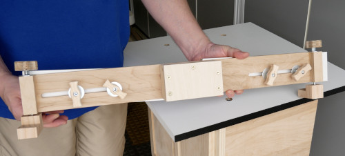 From the back, you can see the clamps on the ends, the knobs for the fence splits, and the box for the dust port.
I didn’t cut a hole for a dust hose, because I didn’t know what size hose you’d be using.
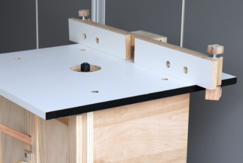 Here it is in place.
The Result (and power switch)
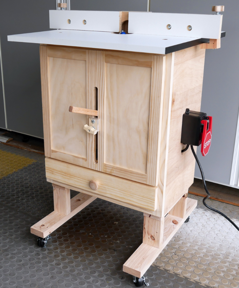
This power switch is just held on by double-sided tape. So you can either buy this switch from me, or supply your own.
Closing
I know this article isn’t perfect, but it’s good enough for now. Especially since it took me four hours to put it together. 🙄
Comments
Now you can comment as a Guest!
You won't receive email notifications of my replies, though.
- Use any name.
- Use test@example.com for your email address.
- “Check” all the boxes. Since you’re using a fake email address, it doesn’t matter what you agree to. 😛
I’ll have to approve your comment, but as long as you’re not spamming me, that’s no problem. Just remember that I do sleep sometimes, or I might be in the workshop, so I might not approve it right away.